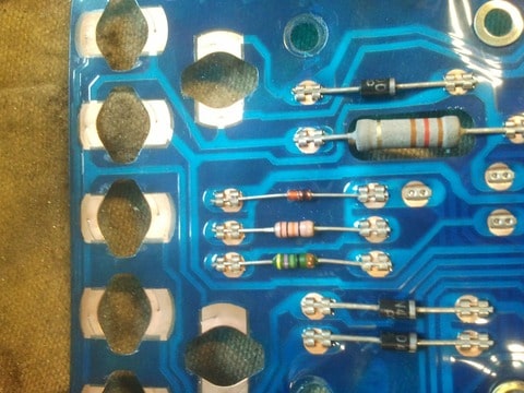
I've removed all the resistors from the old cluster!!
Nolan's 340 pick up D-project F7p (need help for Vss)
Re: Nolan's 340 pick up D-project F7p (need help for Vss)
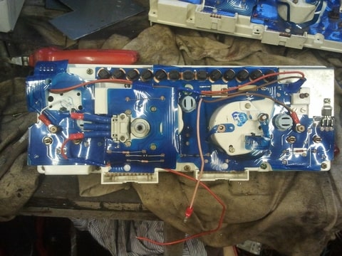
I've taken the + from the horn and the same for the ground. In the middle (A), i've connected the wire from the module and another wire from Eprom (A6 primary speed sensor wire)
I've removed all the resistors from the old cluster!!

I've removed all the resistors from the old cluster!!
Re: Nolan's 340 pick up D-project F7p (need help for Vss)
The problem is:


Don't know where was each one!


Don't know where was each one!

Re: Nolan's 340 pick up D-project F7p (need help for Vss)
These three you need! (found a old picture
The - (negative is really close, the white wire in the picture) Don't mind the other wires..
Re: Nolan's 340 pick up D-project F7p (need help for Vss)
You have taken the resistors from an old speedo? Or just picked up from your actually speedo?
I don t think having a green resistor from the old dash?
thx
I don t think having a green resistor from the old dash?
thx
Re: Nolan's 340 pick up D-project F7p (need help for Vss)
They should be on the 440/480 dashNolan wrote:You have taken the resistors from an old speedo? Or just picked up from your actually speedo?
I don t think having a green resistor from the old dash?
thx
Re: Nolan's 340 pick up D-project F7p (need help for Vss)
You mean i have to cut around the old dash resistors and connect it to the + ?
I've found a pic from my dash:

It's from a 440
Do you think i can put a 5v module reducer like this:
http://www.ebay.fr/itm/DC-DC-KIM-055L-9 ... 418c3dd9e9
It should be easier, i find 12v with the 3 resistors, maybe one is on the wrong side now...
I've found a pic from my dash:

It's from a 440
Do you think i can put a 5v module reducer like this:
http://www.ebay.fr/itm/DC-DC-KIM-055L-9 ... 418c3dd9e9
It should be easier, i find 12v with the 3 resistors, maybe one is on the wrong side now...
Re: Nolan's 340 pick up D-project F7p (need help for Vss)
You need the three next to each other on the left. Cut them out and wire them in parallel, take notice of the direction they are installed. You need to do the same direction. Tape them together and put them in the + wire.Nolan wrote:You mean i have to cut around the old dash resistors and connect it to the + ?
I've found a pic from my dash:
It's from a 440
Do you think i can put a 5v module reducer like this:
http://www.ebay.fr/itm/DC-DC-KIM-055L-9 ... 418c3dd9e9
It should be easier, i find 12v with the 3 resistors, maybe one is on the wrong side now...
Re: Nolan's 340 pick up D-project F7p (need help for Vss)
Yes, but the problem is that i don't know exactly how the resistors were placed, i don't have the same resistors than yours and can't see exactly with the only picture i have
http://www.hostingpics.net/viewer.php?i ... esized.jpg
http://www.hostingpics.net/viewer.php?i ... esized.jpg
Re: Nolan's 340 pick up D-project F7p (need help for Vss)
I think it was like that:


Re: Nolan's 340 pick up D-project F7p (need help for Vss)
Yeah, i'm going to try it tomorrow, just have to connect the 3 together like on the picture with a wire on each side, the up on +12v, and down on Vss + if i'm right...
Thanks!
Thanks!
Re: Nolan's 340 pick up D-project F7p (need help for Vss)
I have tried as you said, but i find 12v too... is it normal? Should it be connected in series?

I'll try with a 12v-5v converter, i'll be sure having 5v output!

I'll try with a 12v-5v converter, i'll be sure having 5v output!
Re: Nolan's 340 pick up D-project F7p (need help for Vss)
brake servo fixed (but i would prefer to fix it straight but it wasn't possible!)
I'll have to try when it will be fixed on the brake pedal...

I'll have to try when it will be fixed on the brake pedal...

Re: Nolan's 340 pick up D-project F7p (need help for Vss)
The engine always idles at about 2/2500rpm... I've put a 12v/5v converter for the vss, but now the rev counter doesn't work... 

Maybe in case of this i need to connect on Ecu (i'll put a Clio sensor):

I'm actually working on servo relocation and exhaust:


Maybe in case of this i need to connect on Ecu (i'll put a Clio sensor):

I'm actually working on servo relocation and exhaust:


Re: Nolan's 340 pick up D-project F7p (need help for Vss)
ca avance bien 