Page 1 of 9
Damn that blower gone again.
Posted: 13 Apr 2013 03:29 pm
by mac
There still seems to be a whole heap of confusion about exactly how the heater blower system works.
Let us take the example of a post 86 car.
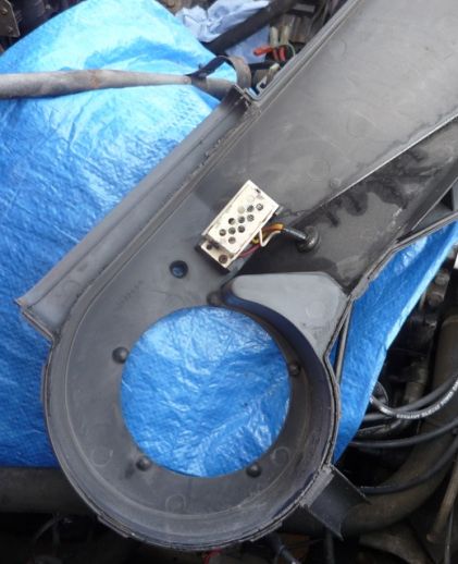
The lower two speeds are controlled through a resistor unit located in the air inlet casing, along side and "downstream" of the blower fan. The high (full) speed does not pass through the resistive coils but direct to the blower through an "Otter" thermal cut out switch located in the same casing as the resistors. The output from the resistive coils also pass through this cut out.
Location of resistor unit,
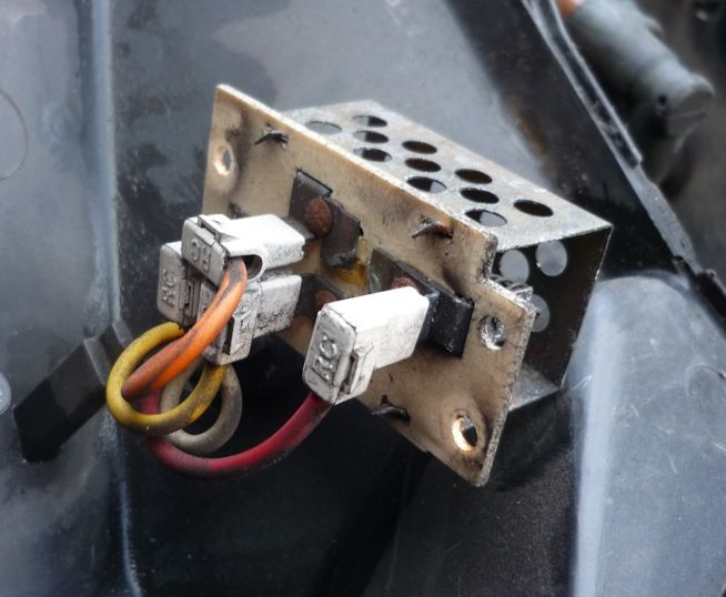
The resistor unit,
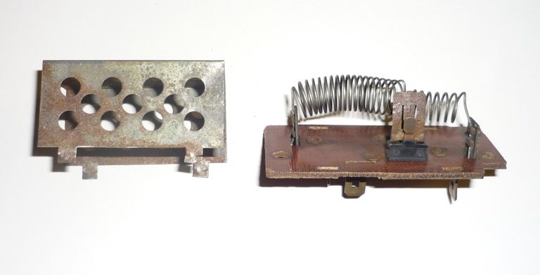
Resistor internals,
The wiring to the resistor unit consists of four wires - Red, White, Yellow and Orange.
The heater fan switch receives 12v+ from fuse19 which itself is supplied by the ignition switched 'X' relay in the fuse box.
Position 1 routes power via the WHITE wire, through both resistive coils, and out to the blower motor via the thermal cut out and the ORANGE wire.
Position 2 routes power via the YELLOW wire through one resistive coil, and out to the blower motor via the thermal cut out and the ORANGE wire.
Position 3 routes power to the pull in coil of an under dash relay. This relay (power contacts) is supplied with permanent 12v+ from fuse 12. The relay routes power via the RED wire, through the thermal cut out, and out to the blower motor again via the ORANGE wire.
The blower motor is connected via a (in the engine bay) two pin plug carrying the ORANGE wire from the resistor unit and an earth.
Work is being done to provide either remanufactured resistor units or some sort of exchange and rebuild scheme. I have removed the air inlet trunking/blower assembly from one of my cars and am setting this up in the workshop to enable me to accurately measure resistor pack temperatures under various conditions. (this should enable us to spec. replacement thermal cut outs correctly).
Mac.
Edited to correct error - the Green Book wiring diagrams are wrong. They show only the "full speed" passing through the thermal cut out. The diagrams show the RED wire supplying the blower - it is in fact the ORANGE. This makes much more sense as the cut out now protects all three speeds.
Thanks to Pettaw for putting doubt in my mind and making me do what I should have done - look at the car not just the diagrams!!!
Mac 19/04
Re: Damn that blower gone again.
Posted: 13 Apr 2013 04:37 pm
by macplaxton
Mac, whilst you were there did you take that temp I was asking about a few months back

Sorry, just skimmed through that. The bench test sound okay, but how are you going to make it realistic?
Re: Damn that blower gone again.
Posted: 13 Apr 2013 05:12 pm
by mac
With the air ducting mounted on the car, and with the fan in place you cannot see the resistor pack.
To get a reliable temp reading I would have to dismantle the unit, fit a thermistor to the resistor pack and reassemble.
(the thermal cut out operates in the fan airflow and I presume is there to guard against a stalled fan on speed three, I also assume if the fan stalled on speeds one and two the current would be wasted through the resistive coils. I don't think the cut out is there to guard against resistor overheat.)
With the assembly on the bench I can operate the assembly in "live" conditions and if I leave out the foam filter I can see the res.pack visually and with an IR thermometer. It can see the air temp as well as the pack temp under differing speeds and conditions. I can also stick a thermistor on the "otter" and measure that directly - it will give me an accurate reading when I stall the motor and give us a good benchmark.
Mac.
Re: Damn that blower gone again.
Posted: 14 Apr 2013 12:19 am
by Ride_on
For consumer products testing we are generally looking for <300K temperature rise on the PCB in a short condition.
I'd like to know the voltages and currents going to the motor. If we could put a bunch of diodes in instead we might not need a thermal cutout.
Re: Damn that blower gone again.
Posted: 14 Apr 2013 09:06 am
by classicswede
A very common problem that does need a solution. I think that a all new unit is the way forward as sending parts back and forth adds costs and with small numbers one unit not getting sent back will cause supply problems.
Glad this is getting worked on.
Re: Damn that blower gone again.
Posted: 14 Apr 2013 10:25 am
by mac
Good thinking Ride_on - I'll stick V & A meters on the jig and get some idea of just what is being drawn when.
Mac.
Re: Damn that blower gone again.
Posted: 19 Apr 2013 10:39 am
by mac
CORRECTION.
Original post now edited to correct mistakes - I believed the wiring diagram in the "Green Book" - It is wrong!!
Thanks Pettaw for putting doubt in my mind.
Mac.
Re: Damn that blower gone again.
Posted: 19 Apr 2013 12:38 pm
by Chris_C
I know I'll be teaching you to suck eggs here Mac, but still, it's always worth a post.
Given the operation (i.e. a bi metallic strip) with a calibrated temperature chamber you should be able to work out the switching temperature of the thermal cutout, with that and the known current draw of the motor speccing a thermal fuse should be fairly easy (10A ones are available from Maplins
http://www.maplin.co.uk/thermal-fuses-470#specification).
Then, either using the same resistor coils un mounted, or speccing power resistors to the job, you have all components covered.
I currently am knocking out a lot of custom PCBs for work, one with the same mounting holes and overall size to take the above specced components would work out around.... £3 per board (ish). Design time for it wouldn't be horrific given the simplicity.
Let me know if you want a hand with any of the above.
Re: Damn that blower gone again.
Posted: 19 Apr 2013 12:44 pm
by macplaxton
@Mac: I was off-duty at the time.....
Re: Damn that blower gone again.
Posted: 19 Apr 2013 05:50 pm
by volvodspec
hows this:
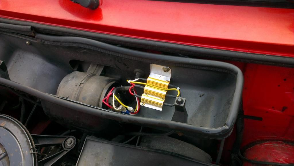
original resistor was broken so replaced it with a few new industrial ones we had lying around, works fine atm and blower speeds are very close to original. it's missing the thermal cutout but i haven't worked out if that's really nescassary at all
*btw, no orange wires present in the older heater housing, just red and brown going to the motor.
Re: Damn that blower gone again.
Posted: 19 Apr 2013 08:14 pm
by Ride_on
I don't know car safety standards, but I would be concerned that the original was not soldered together and needed a thermal cut-out. My estimation is that it is needed for lack of air flow, blocked (say by snow) to prevent major heat rises. Suffient cooling is needed for such an inefficient power controller, this is why I was suggesting before to change to a more efficient switching type, or as I say a bunch of diodes which act more like batteries and drop voltage without significant resistance (0.6V per diode in forward bias).
Re: Damn that blower gone again.
Posted: 19 Apr 2013 09:19 pm
by Fuse
Heater blower in a Volvo 240 has same kind of standard high-power resistors without any thermal cut off as stock, so it's most likely a design issue with the soldered unit like Ride_On stated aboce.
-Marko
Re: Damn that blower gone again.
Posted: 20 Apr 2013 04:24 pm
by mac
A few thoughts,
If we stick with the existing resistive wire coils then we're stuck with crimp type terminations as Nichrome does not lend itself to normal soldering techniques (can be done but with very acidic fluxes - not nice to use).
The thermal cutout is needed to guard against air inlet blockage - the resistors run hot and need the airflow to keep unit temp down.
Could possibly use proprietary wire wound resistors soldered on - but then would need thermal switch to keep things down to below "fall apart temp" - (likely to be around 180c depending on what solder used).
Up to '83' there were only 3 wires to the resistor and speed 3 was not fed by a relay.
The thermal cut out only appears in the green book diags from the '86' supplement - and then it's shown in the wrong place.
The wiring diags show the motor fed by a red wire - from '86' this is orange on the car.
The wiring change seems to have come with the motor/ heater/ ducting change.
Does the "early" resistor pack even have a thermal cutout ?
Perhaps we should abandon originality and look for a more "modern" means of fan speed control?
The floor is open!
Mac.
Re: Damn that blower gone again.
Posted: 20 Apr 2013 04:41 pm
by macplaxton
mac wrote:Perhaps we should abandon originality and look for a more "modern" means of fan speed control?
Perhaps the Big Belgian™ and I should
pay you a visit 
Re: Damn that blower gone again.
Posted: 20 Apr 2013 04:45 pm
by volvodspec
mac wrote:Does the "early" resistor pack even have a thermal cutout ?
yes it does.
biggest question i have, is the thermal cutout there to protect the resistor pack or the heater motor??
the thing is, these new resistors I use will survive quite a bit of heat; my dad wich is a tad more of an electronics genius than me told me that he succesfullely applied silver soldering in a specific case where the normal solder melted (resistors stayed intact!). the solder i used melts at around 350/380 degrees celcius so i don't see problems in using it in this specific case.
the only thing he worried me about was that i simply build a mounting plate, he suggested i redid it to make it also function as a cooling strip just in case it would generate a bit of heat. that would be enough and if eventually the motor would seize/block or whatever it'll just blow the fuse.