So, firstly an apology to Ride_On. It's taken me a ChrisStandardTimePeriod to get to this.
There are only a few pictures as I didn't have my camera nearby and had to use my phone.
First job was to take the 400 series dash and work out what the power supply section was doing to the standard sensor.
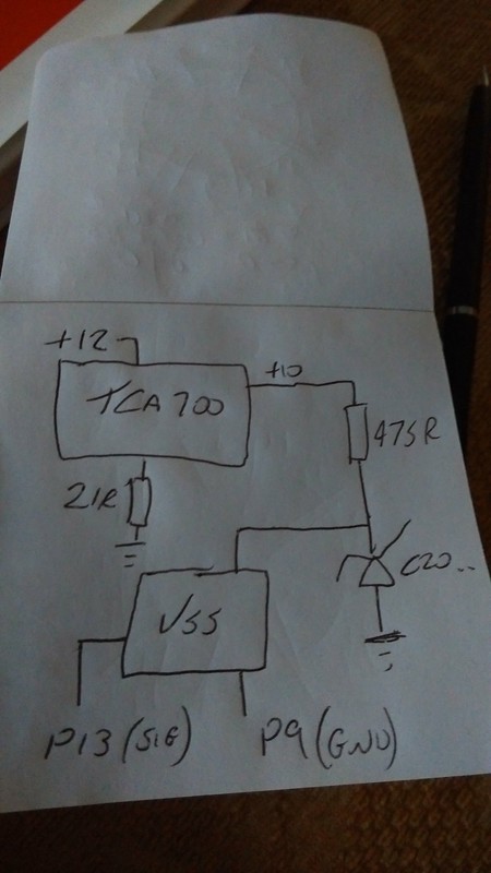
Voltage is supplied via the on dash voltage reg (10 V, datasheet and measured, less than 10 mV ripple measured) and supplied to the Vehicle Speed Sensor (VSS) with a Zener (unidentified, mine is crimped in a way I can't see the last letter(s)). Measured voltage at the Zener is again 10 V, with less than 10 mV ripple.
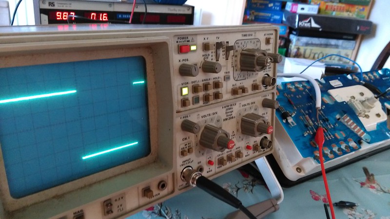
First test was on the original 400 series sensor. 3 - 4 mA current draw measured, Vout at the sig line of the sensor was clean 0 - 10 V square wave with 4 periods over a 360 deg rotation of the speedo head. These periods as far as could be measured were of equal mark space ratio.
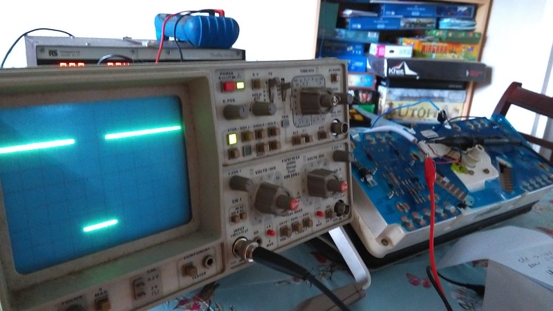
Scope was set to storage mode, an arbitrary time window chosen and the speedo head spun at a representative speed as would be seen during normal use. Output waveform was crisp with negligible rise and fall times.
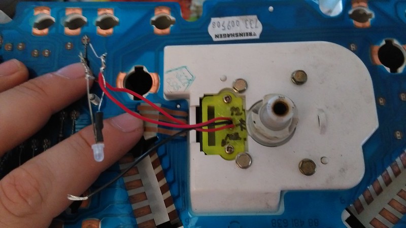
Second test was on Ride_On's sensor. Firstly, the 3D print is of good quality and the fit to the 400 dash was very good. No modification in any respect and screw holes aligned perfectly.
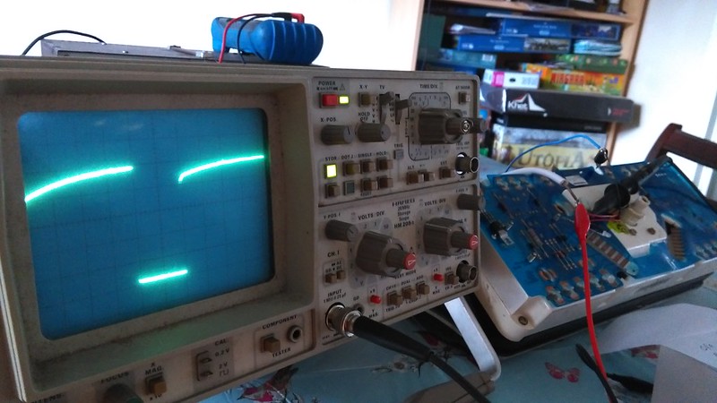
As scope was set to storage mode and so tests would be equivalent, the representative RPM test was conducted. A snag was noted at this point, the rise time of the sensor was significantly different to that of the 400 series original.
I have used the family of sensors that Ride_On is using before and hadn't seen this behavior previously. As can be seen in the photo above, the VSS was supplied with an LED attached to ease testing. It is an ultrabright white LED, total system draw was 19 mA with this attached so on a hunch I removed the LED and repeated the test.
Rise time issue solved. Mark space difference to the original sensor is down to the consistency in the operator spinning the speedo head, not the sensor itself.
All other tests conducted showed clean 0 - 10 V output square wave, 4 periods over 360 degree rotation of speedo head, these periods as far as could be measured were of equal mark space ratio. Current draw of sensor again read 4 mA.
Conclusion:
If Fake was running, I'd have no hesitation of running one of these sensors for a full road test. As far as I can test, they are identical in performance to the original unit.
Ride_On, well done chap. Just sorry again that it's taken me so long!
 LH2.4 is far better than the crappy LE Jet fitted to 360 injections. Carbed 360's are a lot better on fuel, under most situations (eg. except from cold start with choke, probably).