Well Tom kindly sent me over the broken CR-101 to look at and I've got a little bit more life out of it.
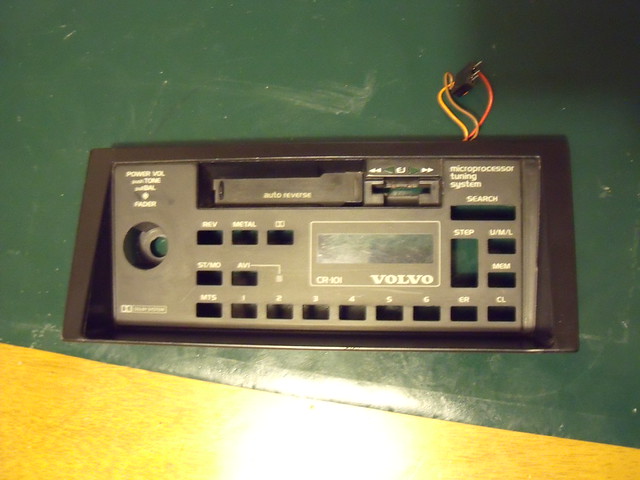
First off the VOLVO CR-101 is also known as a Mitsubishi RX-250VQ and being an older (pre-1984?) radio, the FM band only goes up to 104.00. The later equivalent of it appears to be the CR-4061 (also has 4 speaker output, the CR-4041 is the 2 speaker stereo version). The CR-4060 and CR4040 respectively have a different fascia that fits the 200 series low-mount location and the hole in the > 82MY 300 series dash.
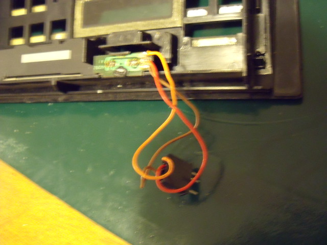
On closer inspection of the set, it looks like someone has been randomly attaching wires to a battery...

Going back to Tom's earlier observations,
1) Earthing the set negative with the black ground wire, and supplying the set with +12V using the blue supply wire, resulted in the cassette deck half of the lights powering up and the deck operating (but not fully tested). This is correctly wired.
2) Earthing the set negative with the black ground wire, and supplying the set with +12V using the red aerial/amp wire, resulted in the radio half of the lights powering up and the LCD showing a fixed 100.65 FM. Set would not seek. This is incorrectly wired.
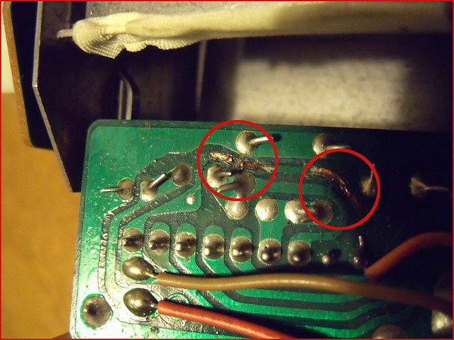
The sub-board with the connector block on it had two burnt looking areas on the green solder resist
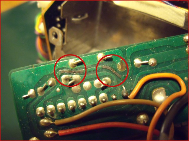
Closer inspection showed that the PCB track in the left hand circle had a 2mm or so break in it.
This was bridged and now the stereo powers up okay. Well, when initially turning on, it displays "100.00" briefly then settles at "U 87.50". I can get the tuner to operate up / down and seek. Runs fine through 87.50 through to 104.00 and back round again. All presets when selected are U 87.50.
I did have to solder the red front panel wire back to the tiny circuit board which lights up the tape direction arrows as it came adrift

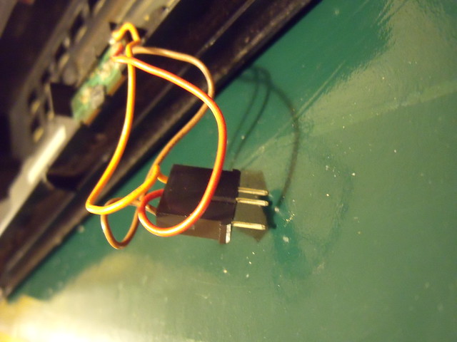
The front panel is connected by a small 3 pin connector block to the cassette deck sub assembly so is quite easy to remove.

If i can get some more action out of the radio, I will probably change the cassette deck belts whilst I have it apart.
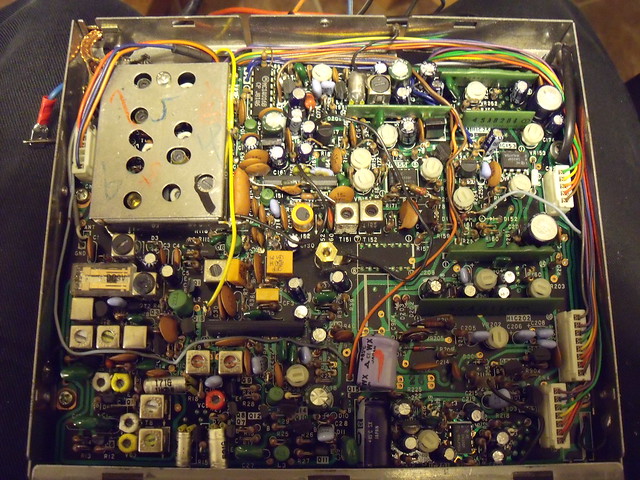
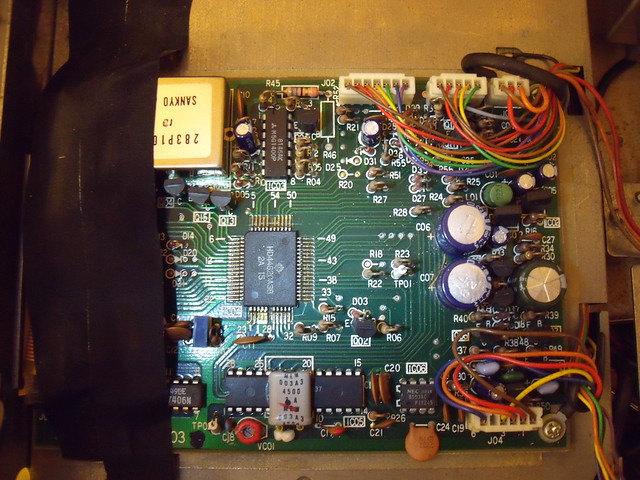
This is the main board, which is visible when the bottom cover is removed.
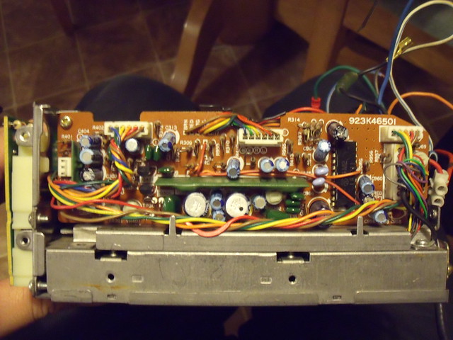
This is the amplifier board which is visible on the left hand side of the unit.

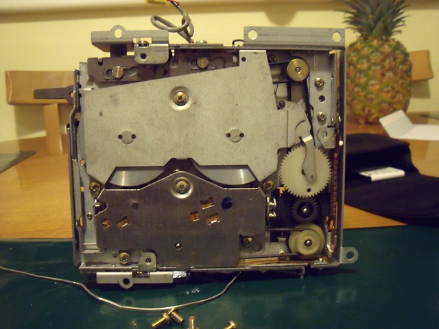
This is something to do with the cassette deck on the right hand side of the unit.
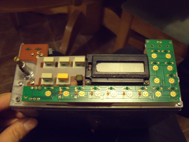
This is the front panel switches / LCD / radio button matrix with the buttons removed. The LCD works fine, despite some leakage on the left hand side.
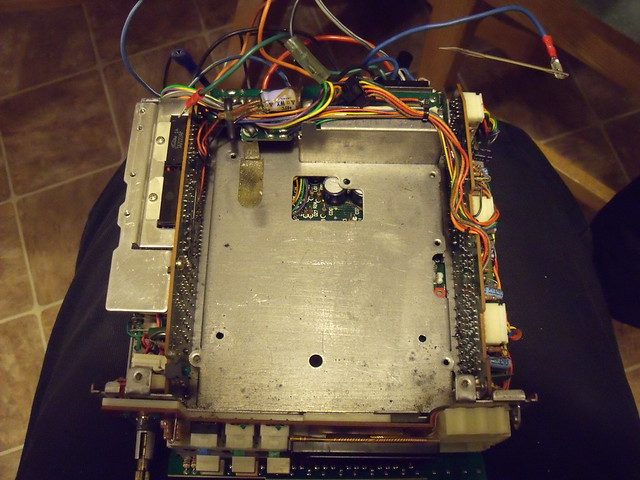
This is the top view of the unit with the cassette deck assembly removed. At the back are the power input board and the DIN sockets board (for an external amp and/or equaliser)
Underneath the cassette deck is yet another board with the radio tuner/microprocessor.
I can't find a datasheet for the 28-pin DIL NEC chip at the bottom of the board (IC05), it is a NEC D1701C, which is something like a PLL tuner chip.
Anyone got any instructions? Most of the buttons appear to work, but I don't get any response out of the U/M/L waveband switch. It just stays on FM. Can't seem to get the MEM button to do the memorising of the presets, but I could just be doing things in the wrong order. Anyone know what the "ER" and "CL" buttons do when they are at home? Didn't get any action out of these, but I don't know what to expect of them even if I could.

Cheers,
Rich