SECTION 1: RENAULT COMPONENT REMOVAL/VOLVO COMPONENT FITTING
If you have a 1.7 engined volvo and are using the parts from that engine, remove the engine from the vehicle first. Certain parts will not be removable if the engine is still in the car.
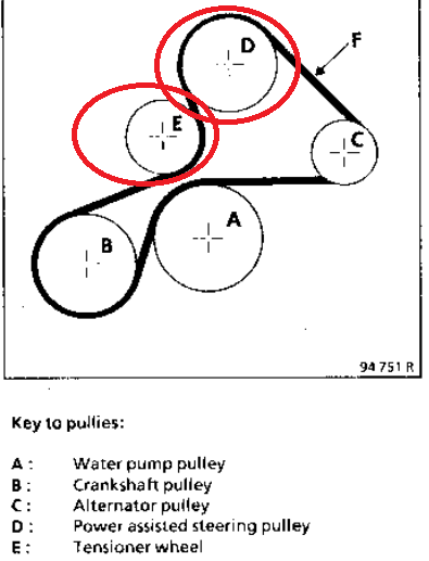
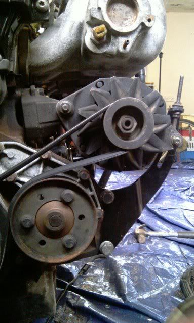
1. PULLEYS.
The first step is to remove the two pulleys that wont be needed for when the engine goes into the volvo. These are the powered steering pump and pulley, and an idler pulley. These are shown in the diagram below, circled in red.
To remove the pulleys, firstly remove the alternator and drive belt by removing the alternator pivot bolt and the bolts holding it to the inlet manifold. Once thats out of the way, the rest of the bracketry can be removed with ease, by removing all the bolts holding them in place. Both the power steering pump, pulley, and idler are attached in one unit, so when removed, will come off as a whole.
there are two bolts at the front (make sure to keep hold of all the bolts removed, as these will be used for mounting the volvo engine parts)
and the rest are on the side. (also remove the inlet manifold brace, seen at the top right corner of this pic)
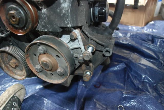
once removed, you should have the side looking something like this
The top 3 bolt locations are now used for the top volvo alternator mount
The lower 4 are used for the left hand volvo engine mount (top right one not used)
The 2 front locations are used for the alternator tensioner
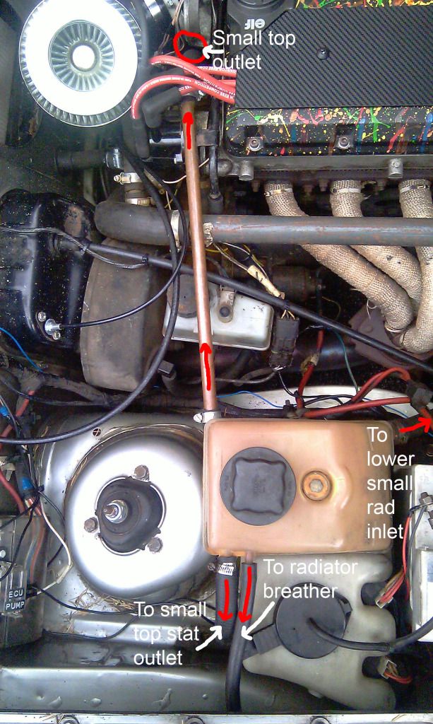
(Before the LH engine mount is bolt on, it is a good oppurtunity to fit (if you have it - not needed if your not running the volvo heater matrix) to fit the metal 1.7 volvo t-piece, to replace the straight renault pipe, that exits the back of the water pump. This will be covered in the water pipe section of the guide too.)
Left hand engine mount
Lower & Upper Alternator mounting points
You can then fit the shorter aux belt. I used one from a Nissan Almera, code 11720~9F610, however, so long as that code is on the belt, it can be used, no matter what make it is from. It is also the same belt as a 6PK818 belt.
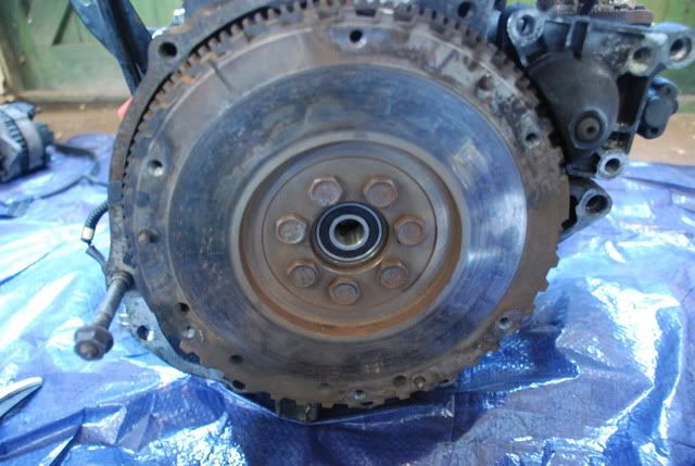
2. CLUTCH & SPIGOT BEARING
To remove the renault clutch (if fitted) undo the six bolts holding the pressure plate to the flywheel, being careful not to round off or lose the bolts (the same ones will be used for the volvo clutch). Once the clutch is off,
REMEMBER TO FIT A SPIGOT BEARING, this is extremely important, as the the input shaft from the clutch bellhousing locates within it, centering it. If you fit everything and forget to fit the bearing, its just a hassle to remove everything again to fit it. If there is one already present, its a good idea to renew the bearing anyway, as it is far more accessible out of the car. I got my bearing off Dai (classicswede) here:
http://www.volvo300mania.com/forum-uk/v ... f=8&t=1804
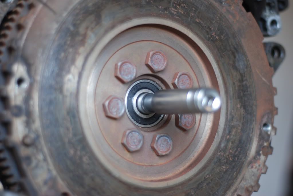
Tap the new spigot bearing home gently, into the flywheel centre, with a suitable drive.
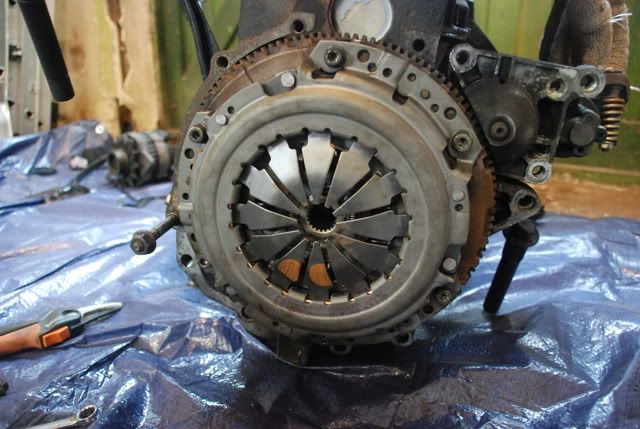
Once thats fitted, the volvo 1.7 clutch can now be fitted (clutch plate, cover plate, and thrust bearing).
When fitting the clutch plate, make sure it is the correct way around, (flywheel marked side toward flywheel

) To centre the clutch plate, I used a deep set 10mm and 14mm socket. The 10mm socket locates within the spigot bearing, and the 14mm socket sits over the 10mm socket, as well as acting as a centre for the clutch plate.
Locate the pressure plate on the flywheel, and hand tighten the 6 bolts originally used for the renault clutch, doing top most bolt, then bottom most, and working your way around, torque them up to TORQUE in the same order.
Finished article
 3. BELL-HOUSING & BEARING HOUSING/INPUT SHAFT
If you have a 1.4 engined 340, you will need a 1.7 bell-housing AS WELL AS the bearing housing/input shaft. The 1.4 version of the shaft is shorter. You will also need the 1.7 engine mounts and 1.7 bell-housing bolts.
Bolt size are as follows:
M10 x 1.5mm pitch grade 8.8 or better (important!) hex headed
3 x 125 long, thread length 30
1 x 90 long, thread length 27
1 x 55 long, thread length 29
(thanks To Alex Laidlaw for those)
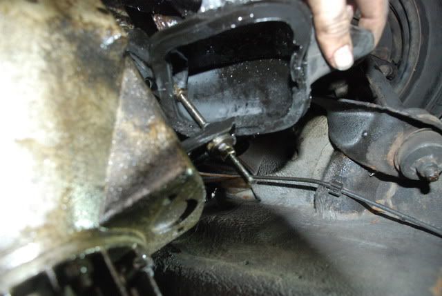
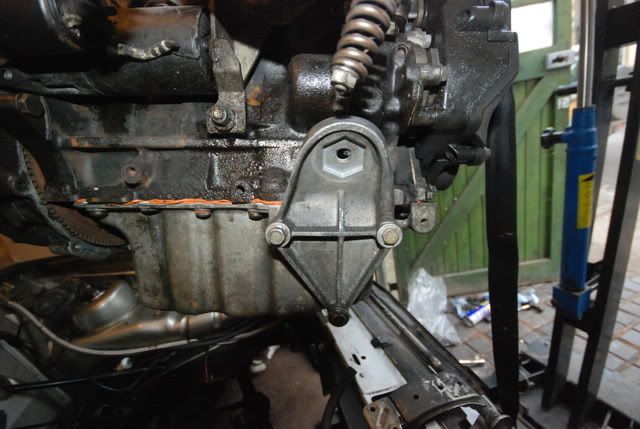
Disconnect the clutch cable at the housing end, underneath the rubber shroud.
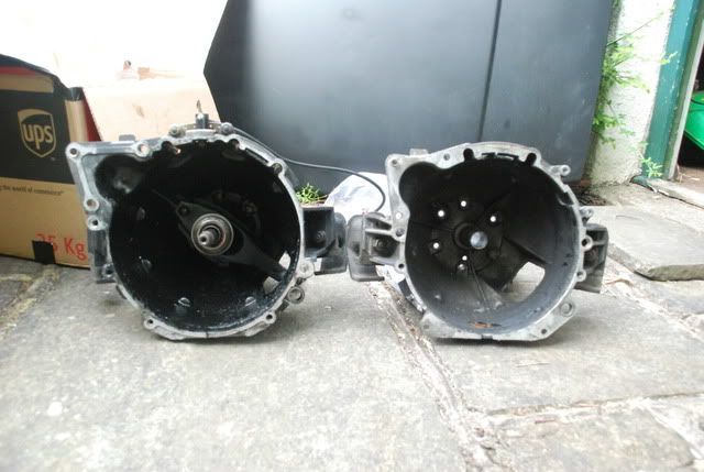
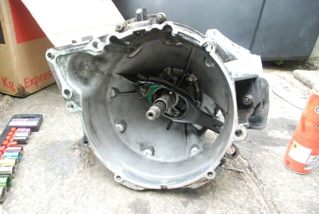
Remove the 1.7 bell-housing and bearing housing if needed, as well as the galvanised blanking plate. Here it is a good idea to replace the clutch release bearing, as it is easily accessible. Below, the difference between the 1.7 and 1.4 housings can be seen (1.7 on left), as well as the clutch release bearing location.
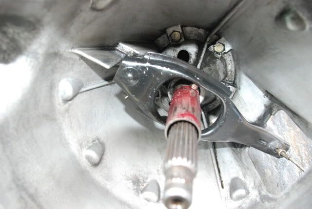
To remove the bearing, press in the spring clip points that hold the bearing lever onto the housing (top left of lever), and move the lever forward. Then, twist the bearing counter clock wise and pull it out. Before replacing it, re-grease the bearing shaft, and put the new bearing in place, making sure it is located on the release lever. Twist the bearing so it locates, and replace the spring clip. Test the action of the assembly by moving the lever up and down from the outside of the housing. It should NOT fall off its pivot point. If it does, re do the spring clip.
Bearing removed
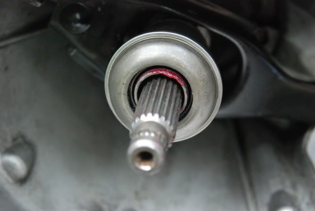
Shaft greased
New bearing fitted
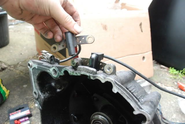
Fit the renault flywheel sensor, at the top of the volvo bell-housing. (renault sensor in my hand)
To make the fitting and locating of the input shaft into the spigot bearing, I loosened the bearing housing bolts, but not enough for the housing to be completely removable. I then located the bell-housing and shaft onto the engine, and loosely located the bell-housing bolts onto the engine, and tightened until the bolt face was touching the housing face. I then did up very gradually the bearing housing bolts, which gently pushed the input shaft into the bearing on the flywheel. I did the same for the bell-housing bolts as well, gently tightening them until they were tight enough to be torqued up.
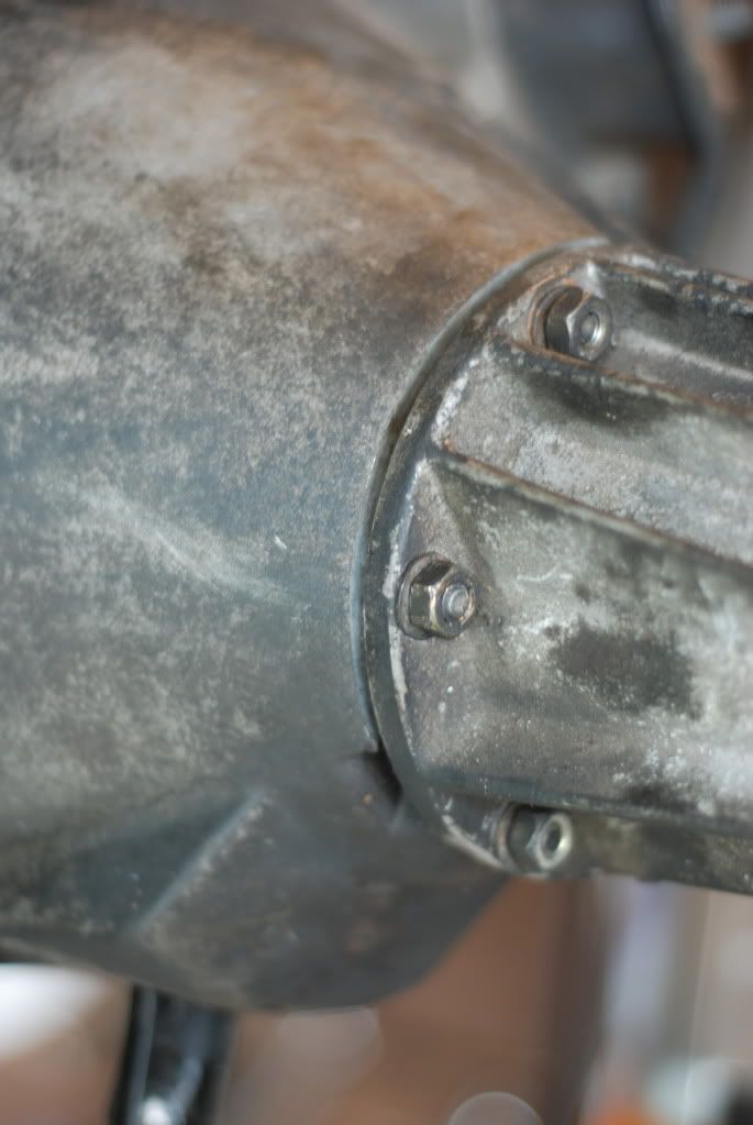
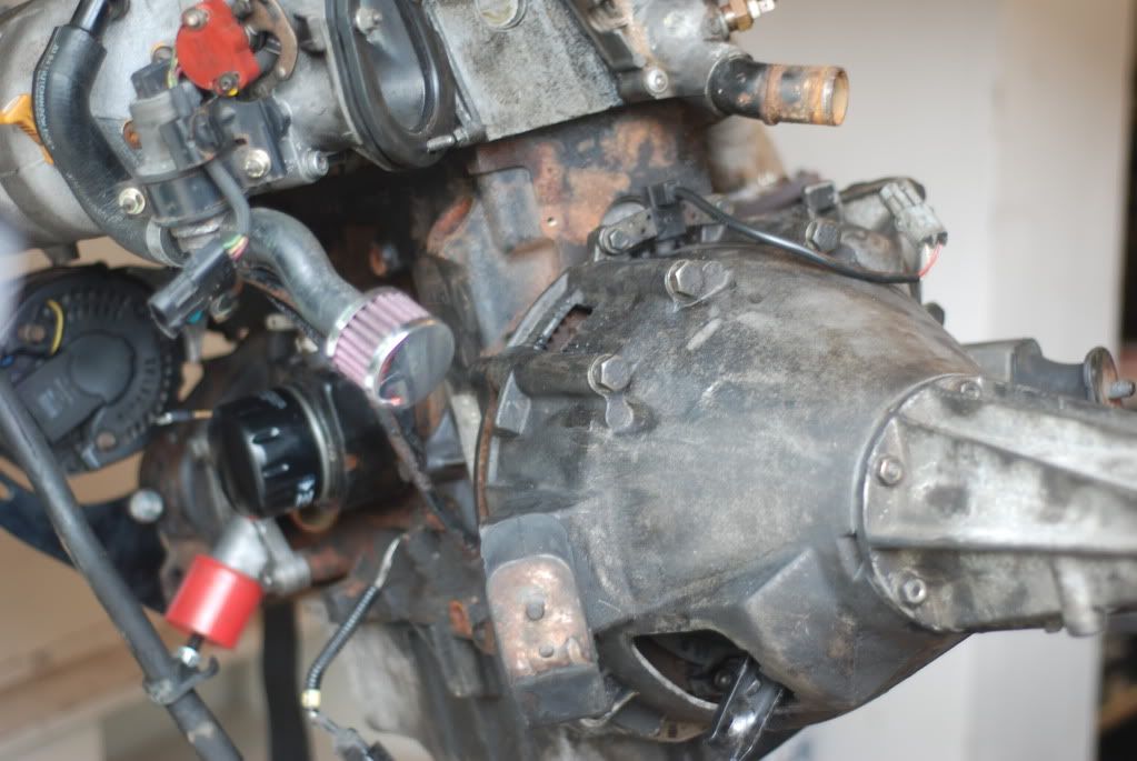
The galvanised plate will be fitted once the 1.7 sump has been fitted, as it is easier to do it in this order. The plate protects the exposed flywheel/clutch components from road debris.
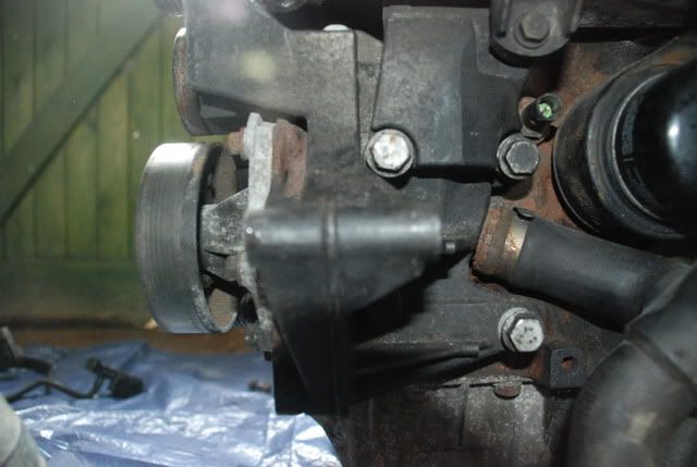
 4. WATER TEMP SENDER & STAT HOUSING
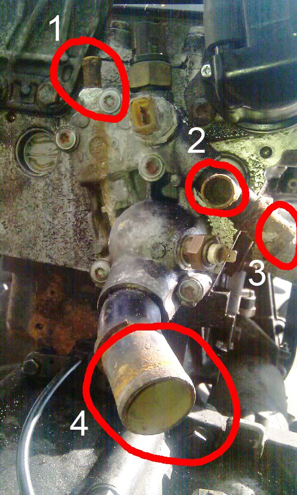
Take the water temp sensor from your water pump on your volvo engine (either the 1.4 or 1.7 will fit and work). The 1.4 sender is located here:
Then, simply unscrew the renault sender here:
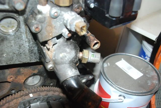
and screw in and tighten the volvo sender.
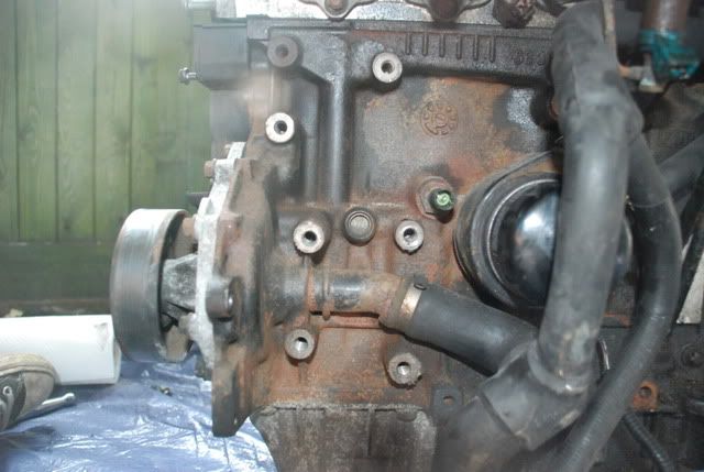
If you want to, use a thermostat housing from a Renault 19, as that housing sends the pipes in a more suitable direction as opposed to the clio one. It bolts to the same points as the clio unit. I didnt use a R19 housing, as I routed the pipes in a different way, because of the future ITBing (you can also just make do and route the coolant hosing however you want, there is no specific way of routing it. Just be careful of the hot exhaust manifold and rubber hosing!). The differences between the two are in the image below.
IMAGE
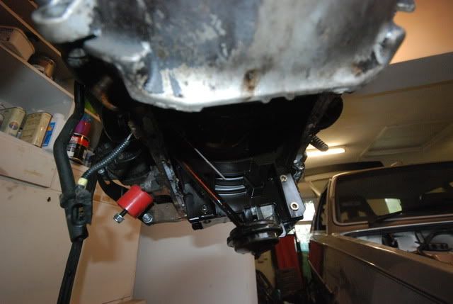
5. SUMP/RH ENGINE MOUNT
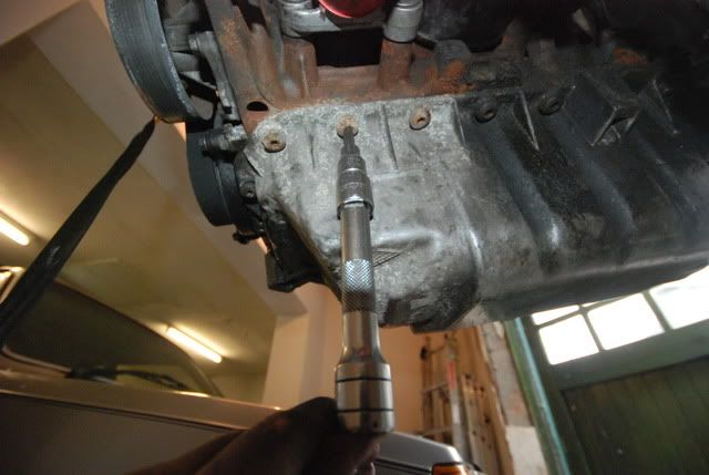
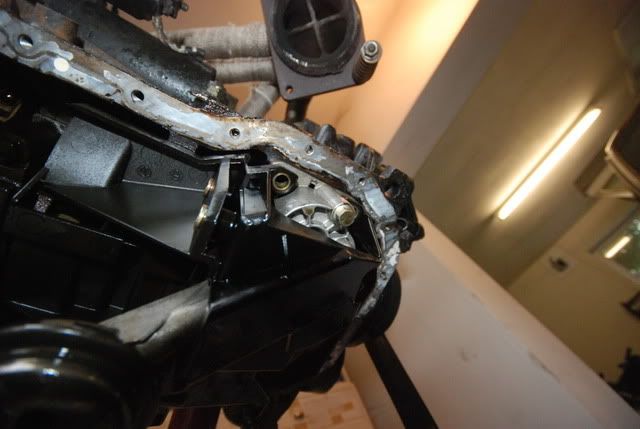
Remove the clio sump by undoing the Torx 40 bolts. Here, I'd highly recommend some high quality torx bits, to prevent rounding of the bolts. I also tapped the bit into the bolt, ensuring a good even distribution of load when undoing, as they are more than likely pretty stiff! There are several hidden bolts at the rear end of the engine, so make sure you remove all the bolts before hitting it with a hammer to remove the sump from its gasket.
Undoing the torx bolts
The removal of the sump will reveal the oil pump.
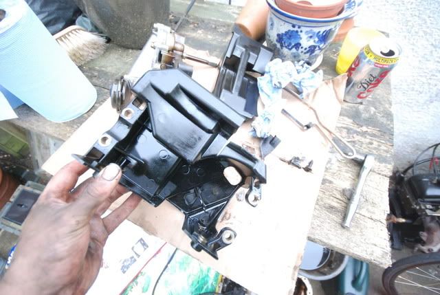
This needs to be modified slightly to fit the volvo sump. To remove it, undo the four bolts holding it to the engine.
Gently guide the pump down from the engine, and then remove the oil pump from the plastic shroud. (It makes trimming the plastic easier, as well as preventing plastic bits from entering the pump). There are 4 torx bolts holding the two halves of the shroud together.
This is the corner that needs to be trimmed
Test fit the assembly by placing it within the volvo sump. The pump mounting points should be flush with the sump top. If not, trim the plastic until it fits.
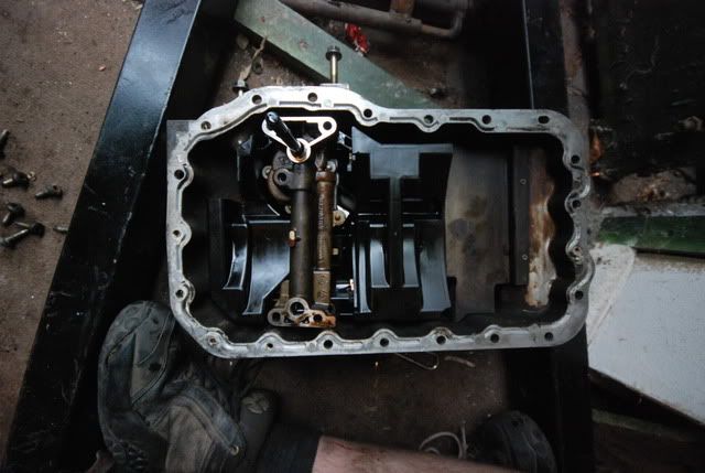
Re-fit the oil pump, making sure the pump shaft splines align with the drive gear inside the block.
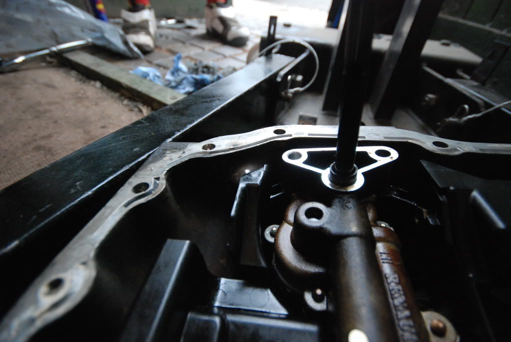
Before the sump is fitted, remove the dipstick, as well as the clio oil gauge sender from the engine. This makes the fitting of the sump easier, as nothing is in the way. The clio sender can be removed completely, as it was used for the clio oil gauges. The volvo 1.7 block has a blanking plug that can be swapped over, otherwise you can leave the sender there to use with some clio gauges, or cut the wires off, as well as the plastic that sits inside the sump. I cut them off.
The sump can now be fitted to the renault engine, with a new gasket and sealant. I used a gasket from a volvo 480 turbo. Tighten the sump bolts to 13Nm. The galvanised blanking plate can now be fitted to the rear end of the block. There are two indents on the plate, that locate on the sump. Fit the plate with the pressed "X" pointing outwards. If its the other way around, it will foul the flywheel. My plate needed the two indents modifying, due to the thicker gasket used.
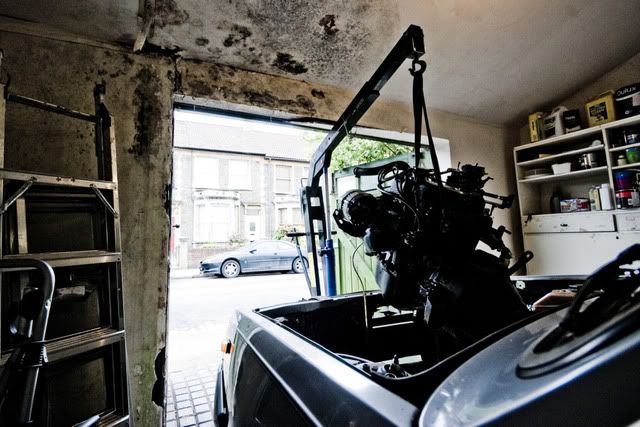
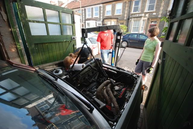
NOTE: When lowering the engine into the car, I did not fit the sump until the engine was most of the way into the car, due to clearance issues. This may be easier for you also. Once the engine is lowered part way into the engine bay, fit the sump and RH engine mount. Then lower the rest of the way.
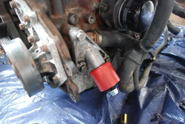
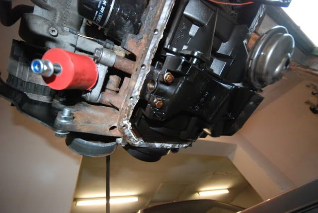
The right hand engine mount fits onto the right hand side of the sump, like this.
The rubber/poly mount can then be bolted to the cast mount.
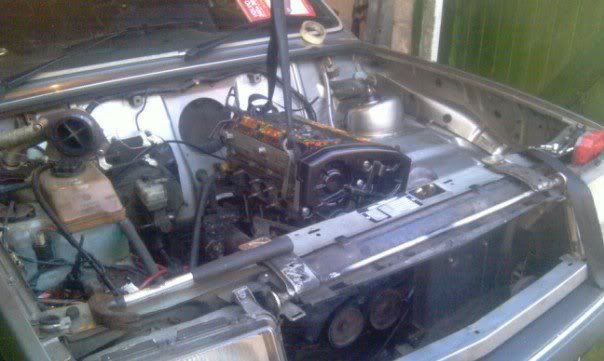
The engine is now ready to be dropped into the car.