***Thread Update to include some correspondence with Shamil that may help others at a later date***
shamil wrote:Sorry I was busy. Thank you very much for posting the diagram. The prevous owner had removed the entire Renix unit replaced it with some other ignition system.
Mark sent me the Renix unit (including all the wiring), distributor, plug wires. Now I want to fix it.
My questions are:
a. How do i keep the ignition timing
b. What is the part mention in diagram D9 (Do i need it?)
Thank you for helping me
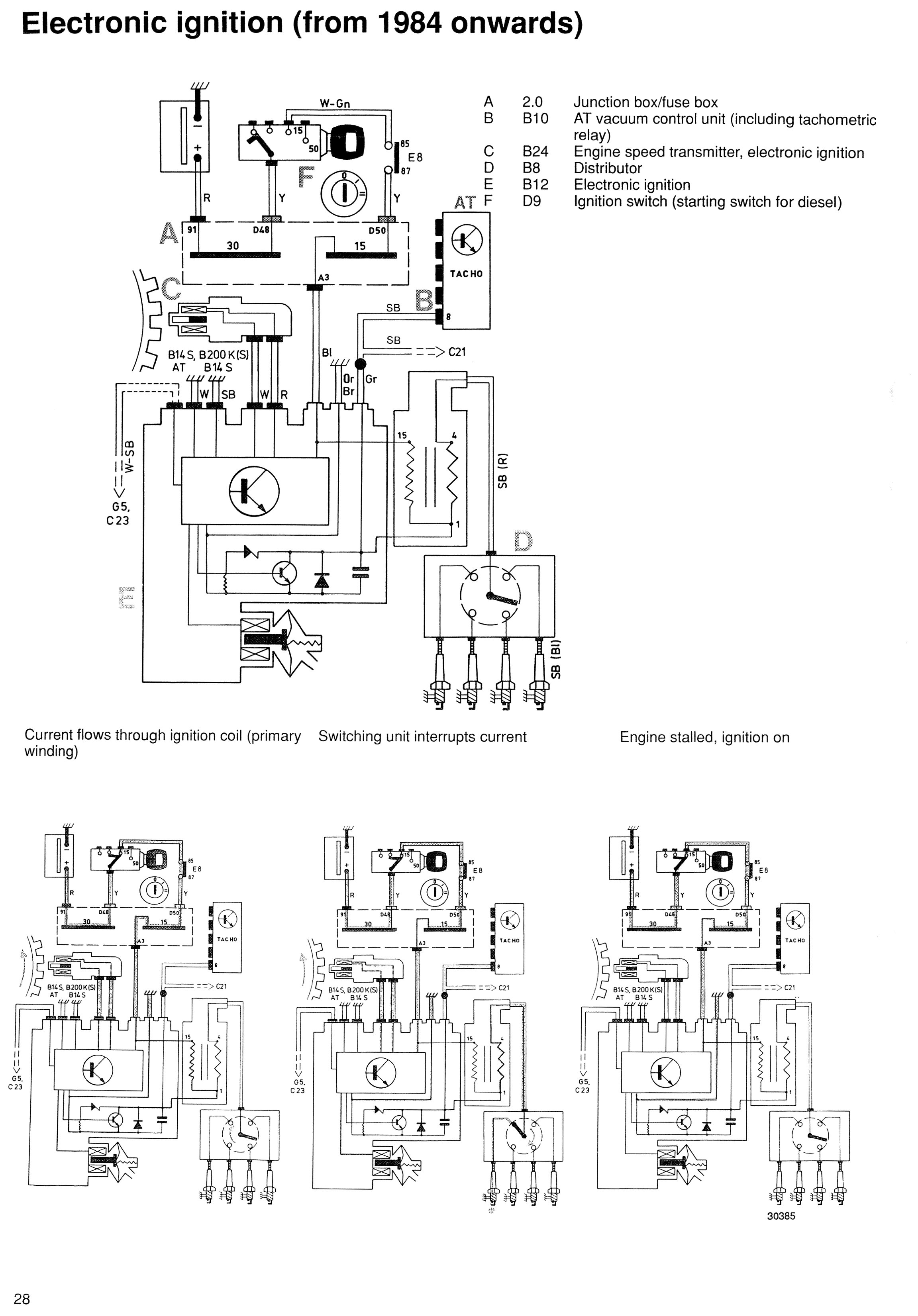
a) The distributor should fit only one way. It is located by 2 pins, see
THIS THREAD. Timing can be checked with a strobe lamp (with the vacuum capsule on the Renix disconnected), but cannot be adjusted. It does not need to be adjusted as the engine position is read by the crankshaft timing sensor. (The flywheel should have a timing pattern on the edge of it). This page might be some help:
Volvo Forum Repairs - 300 Renix
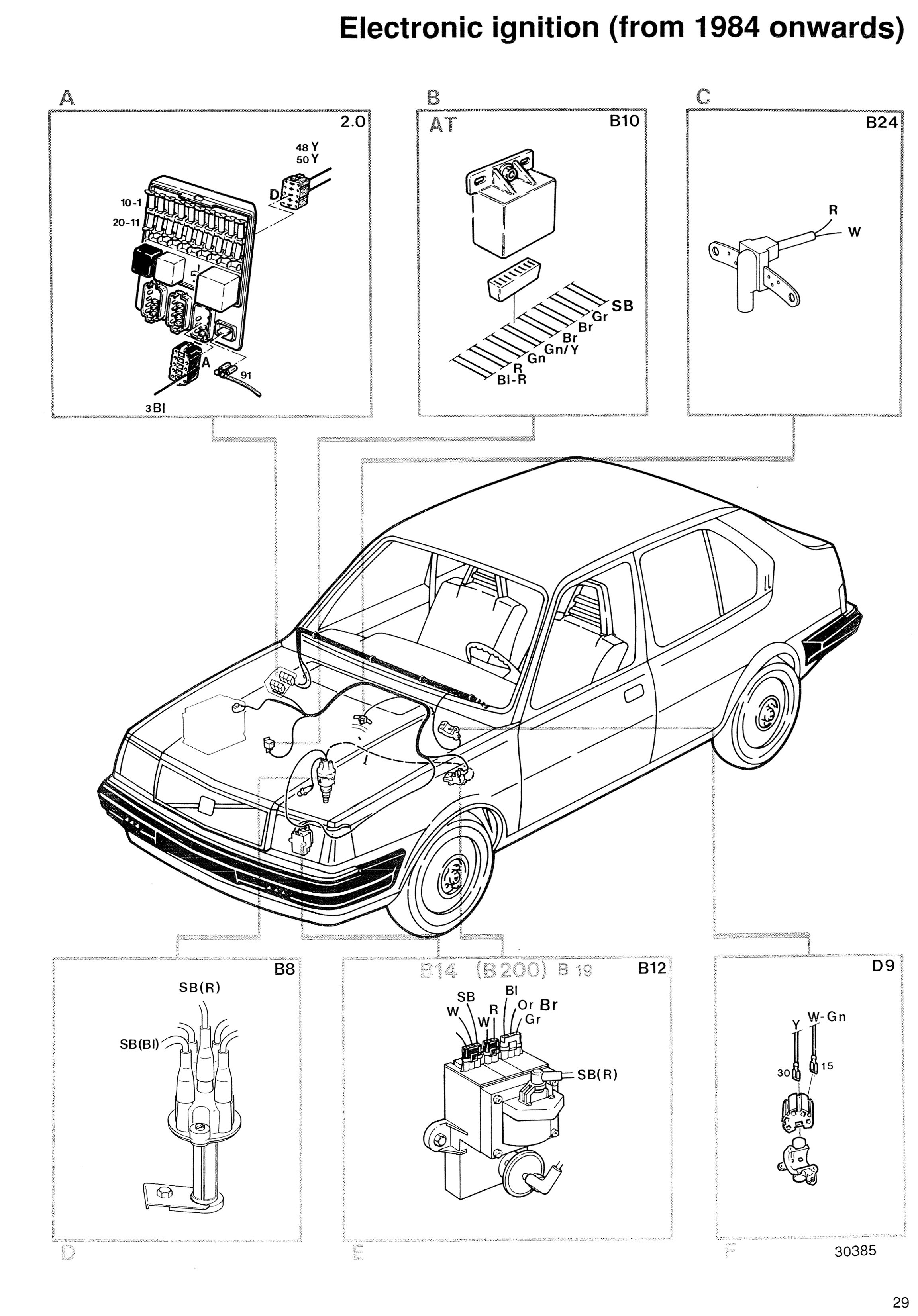
b) The part on the second picture (P29) marked D9 and inside box "F" is just the ignition key switch on the steering column. (Note: diagram shows LHD car).
shamil wrote:...I would like to know what is the AT vacum control unit?
Any references to AT in the Volvo Green Books refers to Automatic Transmission.
***Now a bit of non-Renix stuff - MY87 onwards B14 fuel cut-off***
shamil wrote:Can you please let me know what is that device for (see below) and the wiring diagram?
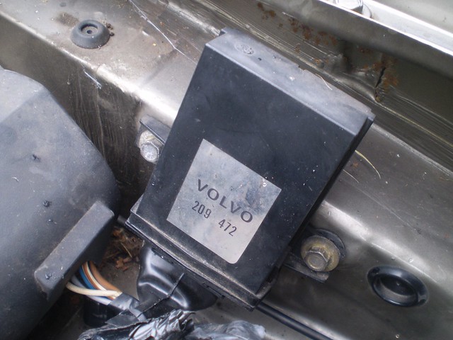
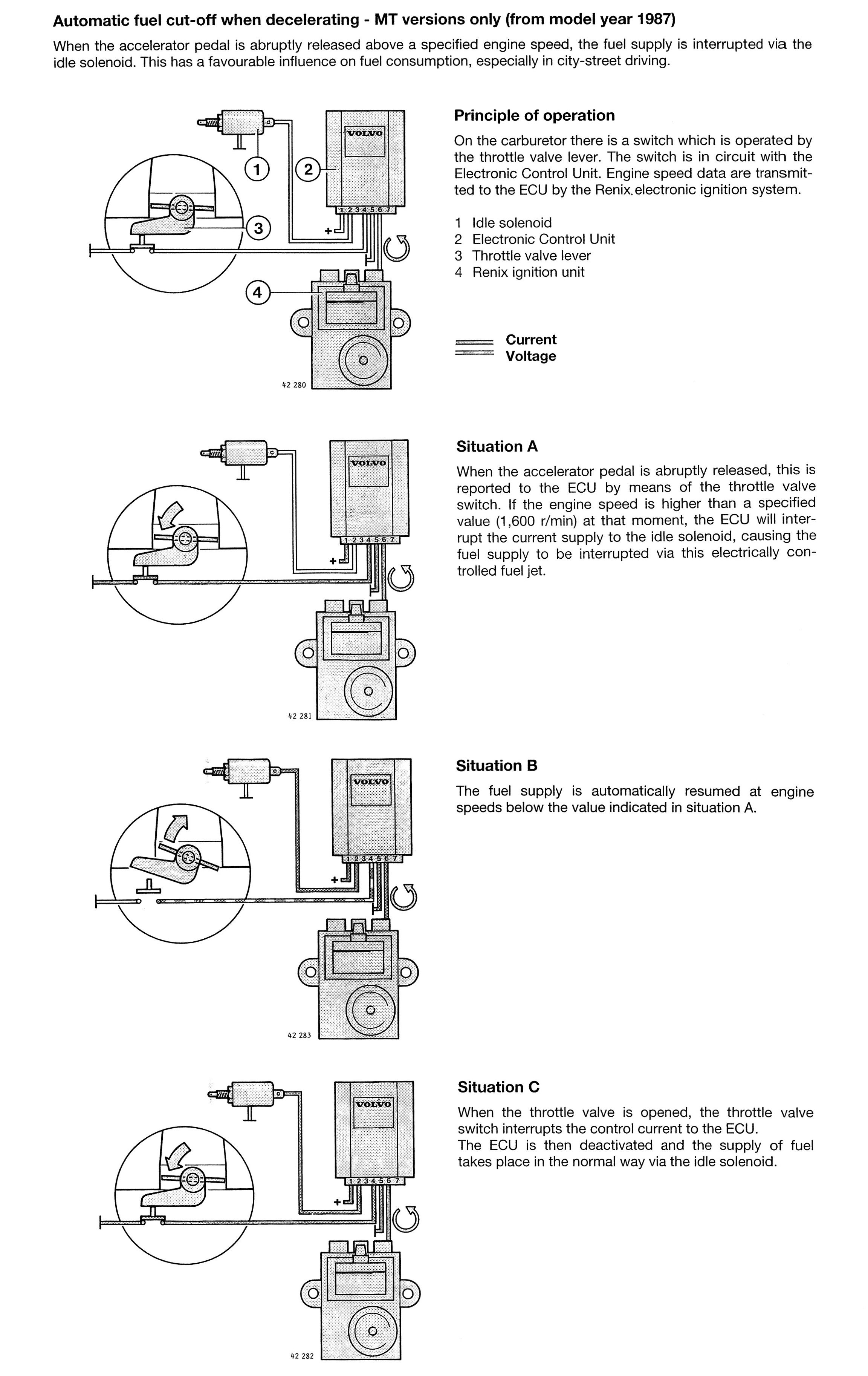
The device is a special fuel shut-off relay (see also
THIS OLD THREAD that has lost its pictures, but
pettaw is pretty much bang-on the money) for 87 MY onwards manual transmission (MT) / B14 cars. Volvo Part No: 3209472.
It is fitted to improve fuel economy.
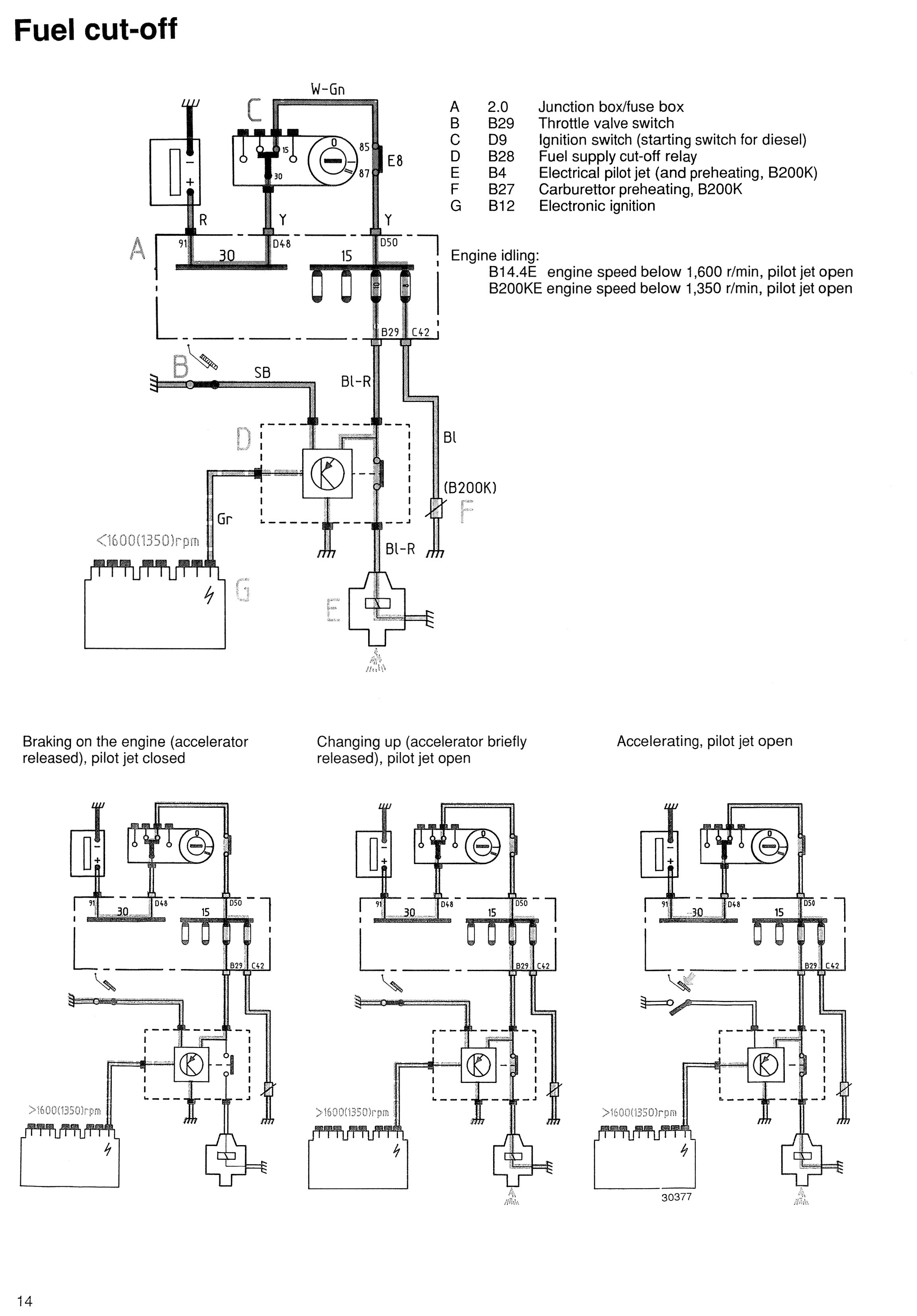
Here's the wiring diagram pics

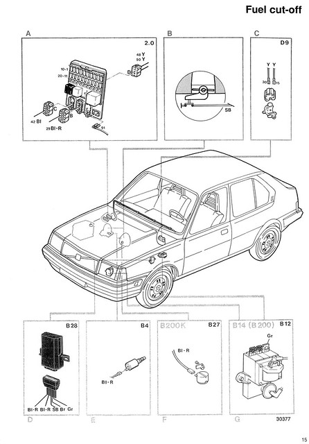
(Click on images for super-large versions)
On older cars without it, the pilot jet stays open all the time the ignition is on. This allows the engine to idle. On cars without it, they will only have ONE blue/red wire to the carburettor idle jet. (Box E on picture 2 (P15)), With the fuel-cut off system, there are TWO wires to the carburettor, ONE to the carburettor idle jet as before, and a SECOND one to the throttle return stop which is black.
Here's a photograph I prepared earlier (just ignore the colour of the wires as it's the wrong carb for the car it was on):
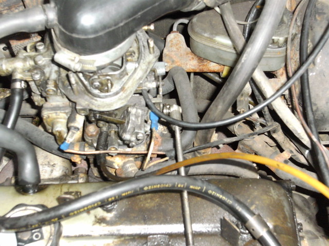
The left one is the electro-pilot jet and the right one is the throttle return stop earth. The carburettor was a Weber 32DIR 109.
A explaination of the fuel cut-off system and its operation is in the Green Book:

Hope this helps.