SECTION 4. ECU/ELECTRICAL CONNECTIONS, MAP SENSOR AND FUEL RAIL
As previously stated, I am using Adam's (340GLT) loom, so I will just be showing how and where to connect his version. I will not be showing you how to make your own. Adam's loom came ready labeled, so all I had to do was find the right connection on the engine and effectively plug & play.
1. INLET SIDE OF ENGINE
Connect the large ECU plug to the ECU. The loom connections will start from here.
Below, the main connections can be seen that connect the volvo loom to the stripped clio loom.
(1.) Connection 3 is a diagnostic port, and connection 4 is taking a rev signal to a rev counter I have installed. You do not need this if you don't want to. Some 340's are lucky enough to have a rev counter already installed. I was not one of these people.
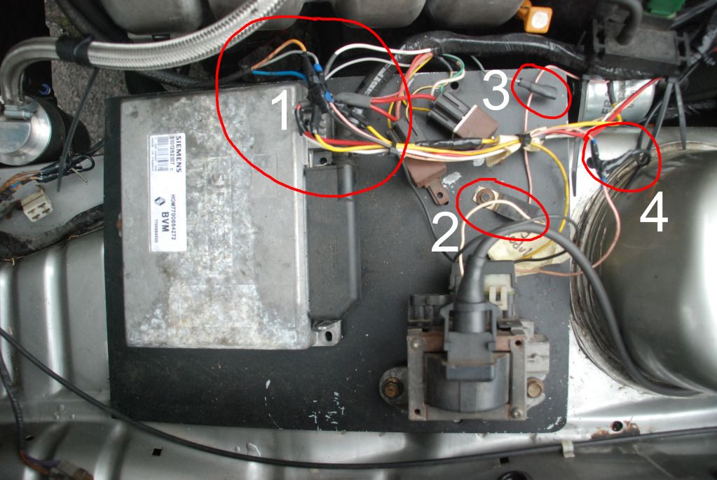
From the 2 pin connector labelled Ignition coil, there should be 3 wires coming from it (pink, yellow, and black). These connect to the grey, blue and orange wires from the volvo loom respectively. The other plug from the ignition coil in the middle needs to be earthed
(2.).
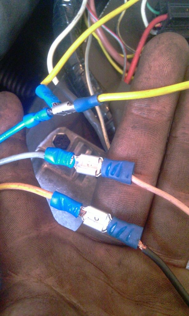
The yellow wire from the actual clio loom is the ignition live (this should come labelled), and needs to be attached also to the yellow wire from the ignition coil. After these connections, they should look like this.
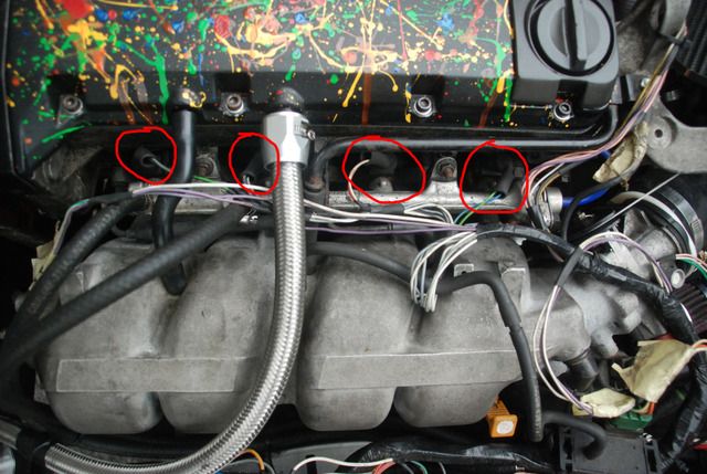
The injector plugs are the four plugs that look identical. The the plug with the shortest length of wire goes to the plug closest to the bulkhead, and so on. You'll know if one of the connections is wrong, as you won't be able to get the rest on. (Injector locations circled in red)
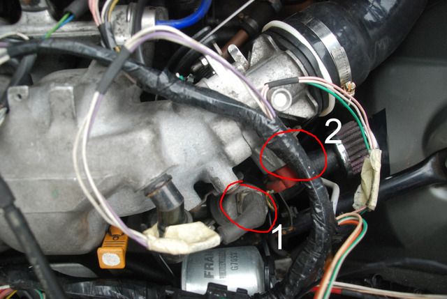
Connect the air flow metre connector (1.) and TPS (throttle position sensor) connector (2.), located here (TPS connector hidden in the picture slightly by the loom):
The fuel tank to fuel rail connections (1.) are shown below, as well as vacuum for the brake servo (2.), fuel pressure regulator vacuum (3.), and MAP sensor (4.).
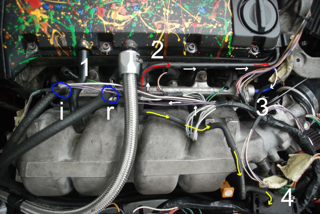
Location 1. shows the Inlet and return outlets of the fuel rail.
Location 2 shows the solid line the goes from an outlet on the inlet manifold around the engine cover to the brake servo. (indicated by red arrows)
Location 3 shows the FPR, with the white arrows showing the routing of the line from it's vacuum port to the FPR (part of the pipe is hidden beneath the servo line in this picture).
Location 4. shows the location and connection of the MAP sensor. The yellow arrows indicate the routing from a vacuum port on the inlet manifold to the sensor. (The actual sensor can be located on the bulkhead if desired, or anywhere else, however mine is here due to the short length of hose I had left from the build.) The sensor connection to the loom is the large 3 pin green plug, which should be labelled "MAP".
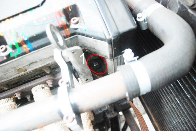
The image below shows the connection location for the air temp sensor, on the end of the inlet manifold (1.) Outlet 2. is an un-used vacuum port, which can be used for the volvo econ gauge if you have one, or it can be blanked off.
 2. EXHAUST SIDE OF ENGINE
The starter motor connections are as follows. The large red cable is the power to the starter, attach the cable loop to the positive starter bolt, and do up the nut. (1.) The yellow/blue striped wire previously used for the volvo ignition switch needs to be cut into (2.), and using a 3 terminal connector, connected to both the long black wire (2.) from the clio loom (signal to the ECU to tell it the engine is being turned over) and the rest of the original yellow/blue wire (this is done because if the black wire is connected directly to the starter motor, the wire can overheat and melt. The thicker striped wire prevents this).
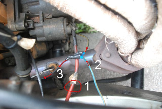
Also, make sure the starter wires are clear from the exhaust manifold and downpipe.
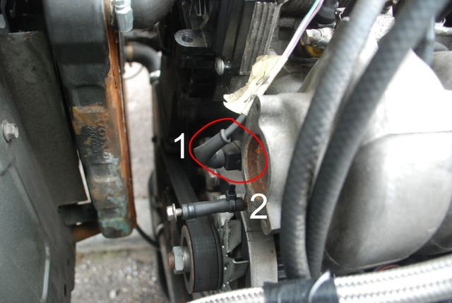
The engine is earthed using the original braided volvo earthing strap, and is attached to the block in this location.
 Make sure to insulate all connections before you connect the battery terminals, and when you are satisfied all the connections are correct and secure.
 Cheers lad.